編輯:關於Android編程
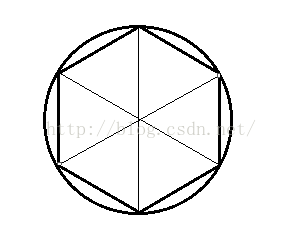 看到圓的內部是一個正多邊形,當我們的正多邊形的邊數(或三角形的個數)足夠多的話,我們肉眼看起來就變成了一個圓。
圓心坐標是很容易確定的,這裡我們假設圓心坐標為(x , y ),然後設圓的半徑為 r 接下來我們需要計算的就是周邊的點的坐標,
看到圓的內部是一個正多邊形,當我們的正多邊形的邊數(或三角形的個數)足夠多的話,我們肉眼看起來就變成了一個圓。
圓心坐標是很容易確定的,這裡我們假設圓心坐標為(x , y ),然後設圓的半徑為 r 接下來我們需要計算的就是周邊的點的坐標,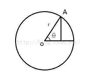 我們很容易計算出來A點的坐標 :
A點的橫坐標為: x + r * cosθ
A點的縱坐標為: y + r * sinθ
我們將圓分成 n 份的話,就可以得到 每一份的角度的值 ,即θ 的值。通過一個for循環我們就可以很容易的得到所有點的坐標。
我們在工程的shape文件夾下新建一個類 Circle , 完成坐標的計算 ,當前代碼如下 (Circle.java ):
我們很容易計算出來A點的坐標 :
A點的橫坐標為: x + r * cosθ
A點的縱坐標為: y + r * sinθ
我們將圓分成 n 份的話,就可以得到 每一份的角度的值 ,即θ 的值。通過一個for循環我們就可以很容易的得到所有點的坐標。
我們在工程的shape文件夾下新建一個類 Circle , 完成坐標的計算 ,當前代碼如下 (Circle.java ):
package com.cumt.shape;

import java.nio.ByteBuffer;
import java.nio.ByteOrder;
import java.nio.FloatBuffer;
import android.content.Context;

public class Circle {

	private Context context;
	private FloatBuffer vertexData;
	// 定義圓心坐標
	private float x;
	private float y;
	// 半徑
	private float r;
	// 三角形分割的數量
	private int count = 10;
	// 每個頂點包含的數據個數 ( x 和 y )
	private static final int POSITION_COMPONENT_COUNT = 2;
	private static final int BYTES_PER_FLOAT = 4;

	public Circle(Context context) {
		this.context = context;
		x = 0f;
		y = 0f;
		r = 0.6f;
		initVertexData();
	}

	private void initVertexData() {
		// 頂點的個數,我們分割count個三角形,有count+1個點,再加上圓心共有count+2個點
		final int nodeCount = count + 2;
		float circleCoords[] = new float[nodeCount * POSITION_COMPONENT_COUNT];
		// x y
		int offset = 0;
		circleCoords[offset++] = x;// 中心點
		circleCoords[offset++] = y;
		for (int i = 0; i < count + 1; i++) {
			float angleInRadians = ((float) i / (float) count)
					* ((float) Math.PI * 2f);
			circleCoords[offset++] = x + r * (float)Math.sin(angleInRadians);
			circleCoords[offset++] = y + r * (float)Math.cos(angleInRadians);
		}
		// 為存放形狀的坐標,初始化頂點字節緩沖
		ByteBuffer bb = ByteBuffer.allocateDirect(
		// (坐標數 * 4)float占四字節
				circleCoords.length * BYTES_PER_FLOAT);
		// 設用設備的本點字節序
		bb.order(ByteOrder.nativeOrder());
		// 從ByteBuffer創建一個浮點緩沖
		vertexData = bb.asFloatBuffer();
		// 把坐標們加入FloatBuffer中
		vertexData.put(circleCoords);
		// 設置buffer,從第一個坐標開始讀
		vertexData.position(0);
	}
}
package com.cumt.shape;

import java.nio.ByteBuffer;
import java.nio.ByteOrder;
import java.nio.FloatBuffer;
import com.cumt.openglestwo_test_one.R;
import com.cumt.utils.LoggerConfig;
import com.cumt.utils.ShaderHelper;
import com.cumt.utils.TextResourceReader;

import android.content.Context;
import android.opengl.GLES20;

public class Circle {

	private Context context;
	private FloatBuffer vertexData;
	// 定義圓心坐標
	private float x;
	private float y;
	// 半徑
	private float r;
	// 三角形分割的數量
	private int count = 40;
	// 每個頂點包含的數據個數 ( x 和 y )
	private static final int POSITION_COMPONENT_COUNT = 2;
	private static final int BYTES_PER_FLOAT = 4;

	private static final String U_COLOR = "u_Color";
	private static final String A_POSITION = "a_Position";
	private int program;
	private int uColorLocation;
	private int aPositionLocation;

	public Circle(Context context) {
		this.context = context;
		x = 0f;
		y = 0f;
		r = 0.6f;
		initVertexData();
	}

	private void initVertexData() {
		// 頂點的個數,我們分割count個三角形,有count+1個點,再加上圓心共有count+2個點
		final int nodeCount = count + 2;
		float circleCoords[] = new float[nodeCount * POSITION_COMPONENT_COUNT];
		// x y
		int offset = 0;
		circleCoords[offset++] = x;// 中心點
		circleCoords[offset++] = y;
		for (int i = 0; i < count + 1; i++) {
			float angleInRadians = ((float) i / (float) count)
					* ((float) Math.PI * 2f);
			circleCoords[offset++] = x + r * (float)Math.sin(angleInRadians);
			circleCoords[offset++] = y + r * (float)Math.cos(angleInRadians);
		}
		// 為存放形狀的坐標,初始化頂點字節緩沖
		ByteBuffer bb = ByteBuffer.allocateDirect(
		// (坐標數 * 4)float占四字節
				circleCoords.length * BYTES_PER_FLOAT);
		// 設用設備的本點字節序
		bb.order(ByteOrder.nativeOrder());
		// 從ByteBuffer創建一個浮點緩沖
		vertexData = bb.asFloatBuffer();
		// 把坐標們加入FloatBuffer中
		vertexData.put(circleCoords);
		// 設置buffer,從第一個坐標開始讀
		vertexData.position(0);

		getProgram();

		uColorLocation = GLES20.glGetUniformLocation(program, U_COLOR);
		aPositionLocation = GLES20.glGetAttribLocation(program, A_POSITION);

		GLES20.glVertexAttribPointer(aPositionLocation, POSITION_COMPONENT_COUNT,
				GLES20.GL_FLOAT, false, 0, vertexData);

		GLES20.glEnableVertexAttribArray(aPositionLocation);
	}

	private void getProgram(){
		String vertexShaderSource = TextResourceReader
				.readTextFileFromResource(context, R.raw.simple_vertex_shader);
		String fragmentShaderSource = TextResourceReader
				.readTextFileFromResource(context, R.raw.simple_fragment_shader);

		int vertexShader = ShaderHelper.compileVertexShader(vertexShaderSource);
		int fragmentShader = ShaderHelper
				.compileFragmentShader(fragmentShaderSource);

		program = ShaderHelper.linkProgram(vertexShader, fragmentShader);

		if (LoggerConfig.ON) {
			ShaderHelper.validateProgram(program);
		}

		GLES20.glUseProgram(program);
	}

	public void draw(){
		GLES20.glUniform4f(uColorLocation, 0.0f, 0.0f, 1.0f, 1.0f);
		GLES20.glDrawArrays(GLES20.GL_TRIANGLE_FAN, 0, count +2);
	}
}
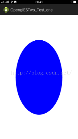 對的,你沒有看錯,它看起來一點都不圓,明明是個橢圓~~ 還記得上一節繪制的矩形嗎,那個矩形根據我們定義的坐標應該是個正方形,但我們的圖示顯示並不是正方形,
而是個長方形,這是什麼原因呢?
對的,你沒有看錯,它看起來一點都不圓,明明是個橢圓~~ 還記得上一節繪制的矩形嗎,那個矩形根據我們定義的坐標應該是個正方形,但我們的圖示顯示並不是正方形,
而是個長方形,這是什麼原因呢?
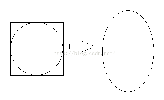 【-1,1】對應的屏幕的像素高與像素寬並不同,圖像在x軸就會顯得扁平了(豎屏時),在橫屏時圖像在y軸就會顯得扁平。
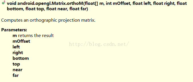 這裡說一下各參數的含義:
float[ ] m :目標數組,長度至少為16個元素,這樣才足以存儲正交矩陣 ;
int mOffset :結果矩陣起始的偏移值
float left :x軸的最小范圍
float right :x軸的最大范圍
float bottom :y軸的最小范圍
float top :y軸的最大范圍
float near :z軸的最小范圍
float far :z軸的最大范圍
這裡說一下各參數的含義:
float[ ] m :目標數組,長度至少為16個元素,這樣才足以存儲正交矩陣 ;
int mOffset :結果矩陣起始的偏移值
float left :x軸的最小范圍
float right :x軸的最大范圍
float bottom :y軸的最小范圍
float top :y軸的最大范圍
float near :z軸的最小范圍
float far :z軸的最大范圍
uniform mat4 u_Matrix;
attribute vec4 a_Position;

void main()
{
    gl_Position = u_Matrix * a_Position;
}
package com.cumt.shape;

import java.nio.ByteBuffer;
import java.nio.ByteOrder;
import java.nio.FloatBuffer;
import com.cumt.openglestwo_test_one.R;
import com.cumt.utils.LoggerConfig;
import com.cumt.utils.ShaderHelper;
import com.cumt.utils.TextResourceReader;
import android.content.Context;
import android.opengl.GLES20;
import android.opengl.Matrix;

public class Circle {

	private Context context;
	private FloatBuffer vertexData;
	// 定義圓心坐標
	private float x;
	private float y;
	// 半徑
	private float r;
	// 三角形分割的數量
	private int count = 10;
	// 每個頂點包含的數據個數 ( x 和 y )
	private static final int POSITION_COMPONENT_COUNT = 2;
	private static final int BYTES_PER_FLOAT = 4;

	private static final String U_COLOR = "u_Color";
	private static final String A_POSITION = "a_Position";
	private int program;
	private int uColorLocation;
	private int aPositionLocation;

	/*
	 * 第一步: 定義投影矩陣相關
	 */
	private static final String U_MATRIX = "u_Matrix";
	private final float[] projectionMatrix = new float[16];
	private int uMatrixLocation;

	public Circle(Context context) {
		this.context = context;
		x = 0f;
		y = 0f;
		r = 0.6f;
		initVertexData();
	}

	private void initVertexData() {
		// 頂點的個數,我們分割count個三角形,有count+1個點,再加上圓心共有count+2個點
		final int nodeCount = count + 2;
		float circleCoords[] = new float[nodeCount * POSITION_COMPONENT_COUNT];
		// x y
		int offset = 0;
		circleCoords[offset++] = x;// 中心點
		circleCoords[offset++] = y;
		for (int i = 0; i < count + 1; i++) {
			float angleInRadians = ((float) i / (float) count)
					* ((float) Math.PI * 2f);
			circleCoords[offset++] = x + r * (float)Math.sin(angleInRadians);
			circleCoords[offset++] = y + r * (float)Math.cos(angleInRadians);
		}
		// 為存放形狀的坐標,初始化頂點字節緩沖
		ByteBuffer bb = ByteBuffer.allocateDirect(
		// (坐標數 * 4)float占四字節
				circleCoords.length * BYTES_PER_FLOAT);
		// 設用設備的本點字節序
		bb.order(ByteOrder.nativeOrder());
		// 從ByteBuffer創建一個浮點緩沖
		vertexData = bb.asFloatBuffer();
		// 把坐標們加入FloatBuffer中
		vertexData.put(circleCoords);
		// 設置buffer,從第一個坐標開始讀
		vertexData.position(0);

		getProgram();

		uColorLocation = GLES20.glGetUniformLocation(program, U_COLOR);
		aPositionLocation = GLES20.glGetAttribLocation(program, A_POSITION);

		/*
		 * 第二步: 獲取頂點著色器中投影矩陣的location
		 */
		uMatrixLocation = GLES20.glGetUniformLocation(program, U_MATRIX);

		GLES20.glVertexAttribPointer(aPositionLocation, POSITION_COMPONENT_COUNT,
				GLES20.GL_FLOAT, false, 0, vertexData);

		GLES20.glEnableVertexAttribArray(aPositionLocation);
	}

	private void getProgram(){
		String vertexShaderSource = TextResourceReader
				.readTextFileFromResource(context, R.raw.vertex_shader);
		String fragmentShaderSource = TextResourceReader
				.readTextFileFromResource(context, R.raw.simple_fragment_shader);

		int vertexShader = ShaderHelper.compileVertexShader(vertexShaderSource);
		int fragmentShader = ShaderHelper
				.compileFragmentShader(fragmentShaderSource);

		program = ShaderHelper.linkProgram(vertexShader, fragmentShader);

		if (LoggerConfig.ON) {
			ShaderHelper.validateProgram(program);
		}

		GLES20.glUseProgram(program);
	}
	/**
	 * 第三步 : 根據屏幕的width 和 height 創建投影矩陣
	 * @param width
	 * @param height
	 */
	 public void projectionMatrix(int width,int height){
		 final float aspectRatio = width > height ?
				 (float) width / (float) height :
			     (float) height / (float) width;
		 if(width > height){
			 Matrix.orthoM(projectionMatrix, 0, -aspectRatio, aspectRatio, -1f, 1f, -1f, 1f);
		 }else{
			 Matrix.orthoM(projectionMatrix, 0, -1f, 1f, -aspectRatio, aspectRatio, -1f, 1f);
		 }
	 }

	public void draw(){
		GLES20.glUniform4f(uColorLocation, 0.0f, 0.0f, 1.0f, 1.0f);
		/*
		 * 第四步:傳入投影矩陣
		 */
		GLES20.glUniformMatrix4fv(uMatrixLocation, 1, false, projectionMatrix,0);
		GLES20.glDrawArrays(GLES20.GL_TRIANGLE_FAN, 0, count +2);
	}
}
package com.cumt.render;

import javax.microedition.khronos.egl.EGLConfig;
import javax.microedition.khronos.opengles.GL10;
import com.cumt.shape.Circle;
import android.content.Context;
import android.opengl.GLSurfaceView.Renderer;
import android.util.Log;
import static android.opengl.GLES20.glClear;
import static android.opengl.GLES20.glClearColor;
import static android.opengl.GLES20.glViewport;
import static android.opengl.GLES20.GL_COLOR_BUFFER_BIT;

public class MyRender implements Renderer {

	private Context context;

	public MyRender(Context context){
		this.context = context;
	}

	Circle circle;

	public void onSurfaceCreated(GL10 gl, EGLConfig config) {
		Log.w("MyRender","onSurfaceCreated");
		glClearColor(1.0f, 1.0f, 1.0f, 1.0f);
		circle = new Circle(context);
	}

	public void onSurfaceChanged(GL10 gl, int width, int height) {
		Log.w("MyRender","onSurfaceChanged");
		glViewport(0,0,width,height);
		//設置投影矩陣
		circle.projectionMatrix(width, height);
	}

	public void onDrawFrame(GL10 gl) {
		Log.w("MyRender","onDrawFrame");
		glClear(GL_COLOR_BUFFER_BIT);
		circle.draw();
	}
}
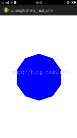 看到我們繪制出了一個正多邊形,看下我們的Circle類 ,其中有個參數
private int count = 10;// 三角形分割的數量
我們只分割了10個 ,大家可以數一下,上面的正多邊形正好是一個正10多邊形,下面我們把這個值改為40,再運行一下:
看到我們繪制出了一個正多邊形,看下我們的Circle類 ,其中有個參數
private int count = 10;// 三角形分割的數量
我們只分割了10個 ,大家可以數一下,上面的正多邊形正好是一個正10多邊形,下面我們把這個值改為40,再運行一下:
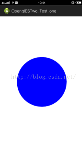 哈 ,我們的圓終於畫出來了~~ ,相信大家連畫橢圓都會了。
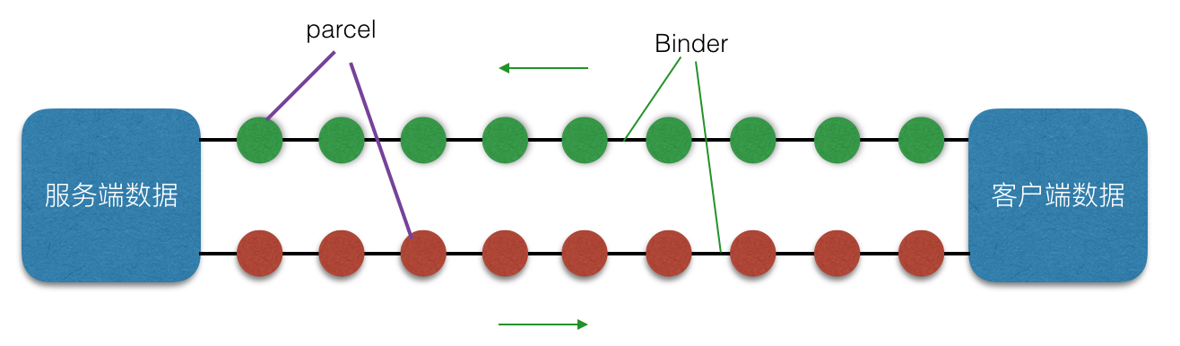 Android AIDL——進程通信機制詳解
Android AIDL, Android進程機制通信機制,這裡就整理下AIDL 的知識,幫助大家學習理解此部分知識!什麼是 AIDLAIDL 全稱 Andr
 Android編程中的四大基本組件與生命周期詳解
本文實例講述了Android編程中的四大基本組件與生命周期。分享給大家供大家參考,具體如下:Android四大基本組件分別是Activity,Service服務,Cont
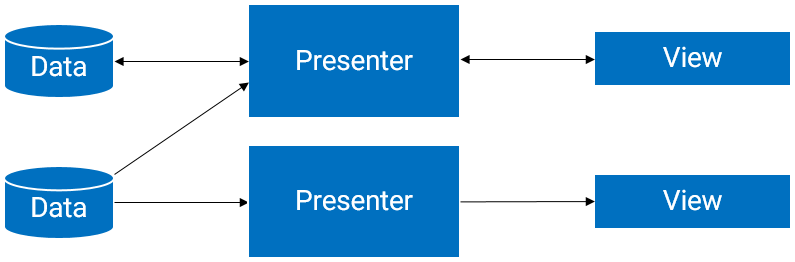 MVP架構實踐
一.MVP理論簡介1.為何要在android中引入MVP??在Android項目中,Activity和Fragment占據了大部分的開發工作。而MVP設計模式可以優化Ac
 Android Studio NDK 入門教程(5)--Java對象的傳遞與修改
概述本文主要Java與C++之間的對象傳遞與取值。包括傳遞Java對象、返回Java對象、修改Java對象、以及性能對比。通過JNIEnv完成數據轉換Java對象是存在於